
For my senior capstone, I had the opportunity to work on a project sponsored by the Jet Propulsion Laboratory. The project involved designing, manufacturing, and testing a Mars Hexacopter Chassis intended for launch on a Falcon 9 rocket and guided descent from a jetpack-equipped capsule to the Martian surface.
Motivation
Since the Mars 2020 Perseverance rover’s successful landing, a new era of controlled flight on Mars has begun, advancing planetary research. NASA’s Ingenuity Mars Helicopter, launched in July 2020, was the first to demonstrate aerial capabilities on another planet, completing 60 flights despite being designed for just five. Ingenuity’s chassis was built to withstand launch and landing loads, extreme thermal environments, and the thin Martian atmosphere, while also housing critical components like batteries, sensors, and heaters. Its success proved that flight on Mars is viable, offering insights that will guide the development of future aerial missions.
The Mars Science Helicopter (MSH) aims to expand on Ingenuity's achievements with greater scale and capability. Unlike Ingenuity’s two two-bladed propellers, MSH will feature six six-bladed propellers to handle heavier payloads and traverse more challenging Martian terrain. Additionally, while Ingenuity took off from a stationary position, MSH will be deployed mid-air during atmospheric entry using a jetpack system, targeting difficult areas like Valles Marineris.
Given the significant differences in design and mission objectives, MSH faces unique challenges. The project seeks to develop a new chassis capable of supporting more demanding payloads and flight dynamics, addressing the limitations of ground-based rovers and advancing the potential for aerial exploration on Mars.

Valles Marineris (The Grand Canyon of Mars)
Fuselage Design
Hexagonal chassis constructed from carbon fiber composite panels, selected for a favorable stiffness-to-mass ratio.
Provides mounting locations for sensors, electronics, and solar cells without compromising structural integrity.
Sized to meet Falcon 9 launch load requirements at 44 kg, under the 50 kg mass allocation.
Tab-and-slot joints between structural members simplify alignment during assembly.
Structural members are bonded using aerospace-grade epoxy adhesive.
Overall envelope conforms to the aeroshell's internal stowage geometry.


Arm Deployment Design
Uses a constant-torque spring for controlled, constant-force deployment, rather than the variable-torque profile of a traditional torsional spring.
Springs can be swapped without disassembling the mechanism, allowing torque values to be adjusted to different requirements.
Dual-spool configuration with custom-sized bushings supports smooth winding and unwinding through the deployment cycle.
Includes a catch mechanism designed to stop and lock the arm at full deployment.
Modular design allows the deployment mechanism to be tested off-chassis, simplifying test setup.
Designed for Manufacturability using both CNC and manual mills and lathes.

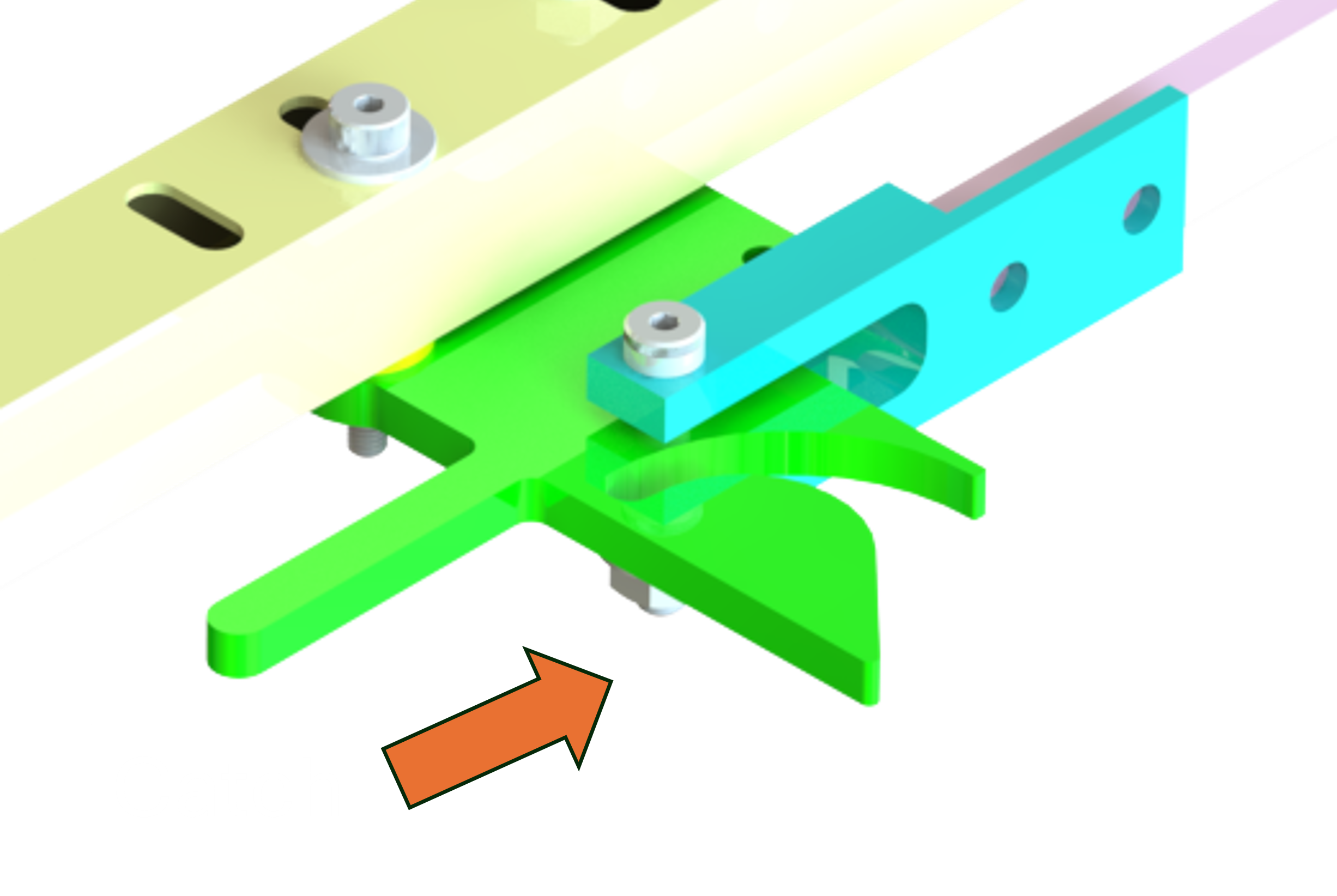


Rotor Deployment Design
Uses a variable compression spring to adjust the preload force on the locking pin, securing the rotor in place.
Designed for machining on a CNC mill.
Designed to lock at 60 degrees of rotation, preventing further slip once engaged.
Modular design allows off-chassis testing with different motors and drill chucks.
Holds six rotor blades and stows them within the chassis frame envelope.


Manufacturing
During this project, I served as the manufacturing engineer while also contributing to the design of the chassis framework and deployment mechanisms. I machined components by hand using self-drafted reference drawings, working with mills and lathes as shown in the slide deck to the right.
I logged over 150 hours in the machine shop, developing hands-on proficiency with mills, lathes, and other equipment. Our total budget was $4,000, with most funds going toward stock material for machining, and the remainder covering outside processes such as water-jetting the chassis frame.


Vibration Testing
To validate the chassis framework design based on Femap simulations, we conducted vibration testing to simulate Falcon 9 launch loads.
Blue Canyon Technologies provided access to a vibration table, where we performed random vibration, sine sweep, and sine burst testing along the XY and Z axes, in accordance with NASA GEVS requirements.
The chassis withstood all applied loads without failure, and the Femap simulation results correlated closely with the measured vibration test data.


This project was one of the most hands-on and immersive experiences of my academic career, spanning the full engineering lifecycle from design and manufacturing to testing and validation.
I'm looking forward to carrying these skills into more complex engineering projects going forward.
